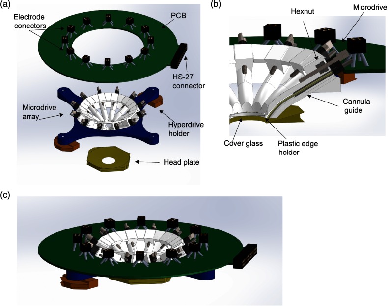
Fig. 1.
Overview of the wide-field imaging hyperdrive. (a) Renderings of the main parts of the hyperdrive: PCB; electrode connectors; HS-27 connector (Neuralynx); circular microdrive array; hyperdrive holders; and headplate. (b) Cross section of the microdrive. The metal screw moves inside the hexnuts glued into the plastic base. The tetrode (not shown) is glued to the microdrive and moves inside the guide cannula, which opens below the coverslip glass. (c) Rendering of the assembled hyperdrive.

