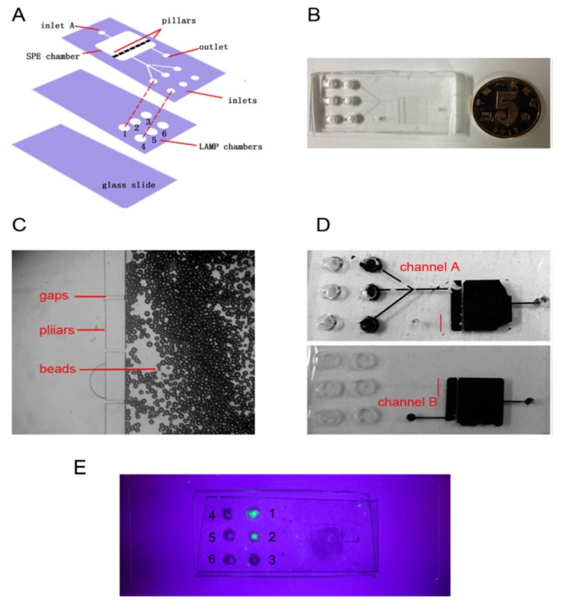
Figure 16.
This microfluidic device consisted of two layers; (A) Schematic design of the device; (B) the real assembled device. The cells, DNA extraction reagents and silica beads are directed to the upper layer through the inlets to the SPE (Solid phase extraction) chamber. Following DNA extraction in the SPE chamber, the DNA samples are washed from the beads using distilled water to the second layer (LAMP chamber). The gaps on the micropillars are small enough to prevent bead transfer to the second layer; Subpanel (C) Shows the SPE chamber in which the beads stuck by the row of micro-pillars and the micro-gaps; (D): the solution flow in the chip is showed by an injection of black ink from inlet A flowed to channel A or B; the positive results can be seen by a, green fluorescence under the UV light (E) [123]. (This Figure is used from Elsevier with permission).

