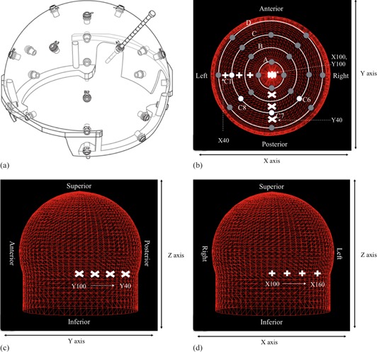
Figure 2.

Hemispherical skull measurement helmet and series of single shot treatment planning used to investigate the change of shot position on skull model discrepancies, showing helmet and ruler (a). Top view (b) of the 24 measurement points in the helmet (dark grey circles; white circles are measurement points C1, C6, C7, and C8); lateral view (c) and frontal view (d) of skull model with all measurement points set to 80 mm. The shot position of y‐axis (c) and x‐axis (d) is shown in white mark.
