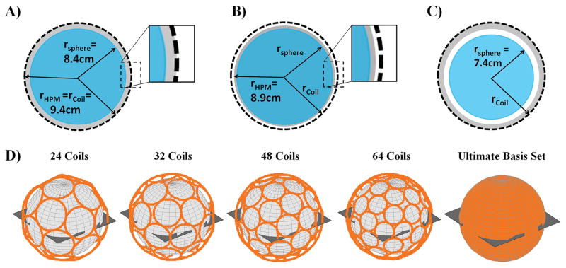
Figure 1.
Various geometrical configurations used for the simulations. (A,B,C) Schematic representations of the homogeneous spherical phantom (blue, rsphere), the spherical surface where the current distribution of the transmit elements is defined (black dashes, rcoil), and the layer of High Permittivity Material (grey, rHPM), is shown for three cases. The fully-filled (A) and half-filled (B) cases used to determine the optimal relative permittivity have set sphere and coil radii. Reduction of the phantom size (rsphere) while the distributed transmit elements and layer of HPM remain fixed is shown as the third case (C), with the smallest phantom size displayed. The simulated transmit array geometries (D), positioned at rcoil and fully encircling the phantom and HPM, are shown, together with the excitation plane through the center of the sample.

