Fig. 1.
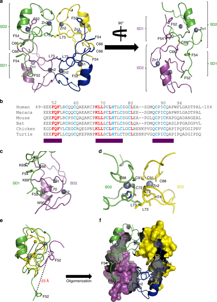
Crystal structure of PML RING tetramer. a Crystal structure of PML RING tetramer. The residues 51–97 of crystallized PML RING49–104 are visible in the electron density map. Four PML monomers are colored in green, magenta, blue and yellow, respectively. The contact residues (F52, F54 and L73) are shown in stick representation. Zn ions are shown in sphere representation. Sub-domain 1 (SD1FQF) and sub-domain 2 (SD2) are bracketed. b Sequence alignment of the PML RING domains from different species. The conserved residues lying in the F52/54-interfaces and L73-interfaces are highlighted in red, while the conserved Zn-binding residues are colored in cyan. The deep purple boxes underneath the sequences are used to highlight the conserved (greater than 5 out of 6) residues among PML RING. c, d Enlarged views of PML RING dimeric interfaces. The residues involving PML oligomerization are shown in stick representation. e Structural superimposition between different PML RINGs. The NMR16 and crystallographic PML RINGs are colored in yellow and green, respectively. L73 positions are labeled with “Asterisk”. The internal Zn–Zn distances and the putative F52Q53F54 swing are highlighted with dash lines. f The buried areas of the SD1FQF/SD2 and SD2/SD2 interfaces are shown in gray

