
Figure 3. A broad set of 3D mesostructures morphable by loading path strategies.
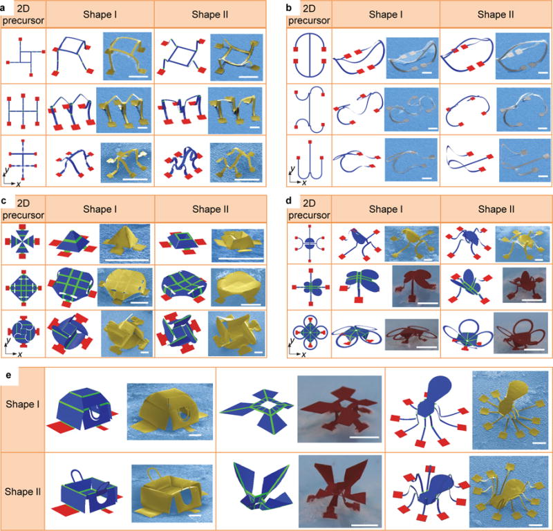
a-d, 2D geometries, FEA predictions and experimental images (SEM or optical) of morphable ribbon-shaped mesostructures with and without creases, membrane-shaped mesostructures, and hybrid ribbon/membrane mesostructures. Path I corresponds to simultaneous release, and Path II corresponds to sequential release (y direction first, and then x direction). e, FEA predictions and experimental images (SEM or optical) of morphable, recognizable objects. Certain parts of the structures are not shown in the FEA results for the second and third examples to improve the visibility of the key regions. The complete deformed configurations based on FEA can be found in Supplementary Fig. 10. In all colorized SEM and optical images, the yellow, silver and red colors correspond to SU8 (6 μm for normal region and 2 μm for crease), silicon ( m) and PET (40 m), respectively. Scale bars, 400 m for samples with SU8 and silicon, and 4 mm for samples with PET.