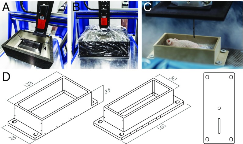
Fig. 1.
Components of the IGMM. (A) Overview of the IGMM showing the milling machine, the liquid nitrogen bath, the inflow valve for the gaseous nitrogen (arrowhead), and the attachment plate for the holders (arrow). (B) Cover around the milling area to keep the cold nitrogen vapor contained. (C) Close-up image of a large holder with an embedded, frozen mouse. Notice the nitrogen vapor surrounding the milling area and the milling bit shown at the top. (D) Drawing of a large (Left) and small (Center) holder and the underside (Right) with two notches ensuring accurate fixation.

