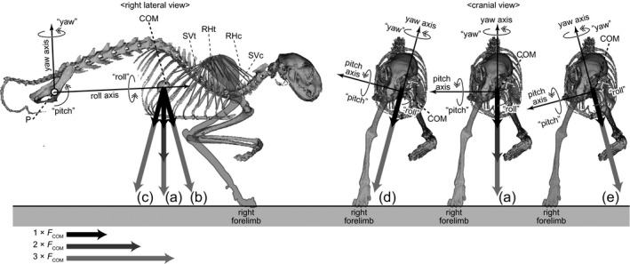
Figure 3.

3D rotation model of Felis constructed in this study shown in right lateral and cranial views. The model assumes a stance on the right forelimb, and the body is supported via thoracic muscles (RHc, m. rhomboideus cervicis; RHt, m. rhomboideus thoracis; SVc, m. serratus ventralis cervicis; SVt, m. serratus ventralis thoracis). The roll, yaw and pitch axes through the acetabulum (point P) are perpendicular with each other. A plane parallel to the roll and yaw axes is defined as the ‘reference plane’. The uplifted body elements are allowed to rotate about the point P. The uplifted body elements are subjected to the downward force (FCOM) at the centre of mass (COM) generated by acceleration, and to the contractile forces of the thoracic muscles (RHc, RHt, SVc and SVt). Moment analyses were conducted under different orientations of the COM acceleration: (a) vertical; (b) 15° anterior; (c) 15° posterior; (d) 15° rightward; and (e) 15° leftward accelerations (see Table S3).
