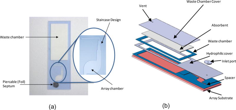
Figure 1.

(a) Photograph of the flow cell with a close-up view of the “staircase” design (b) components of the flow cell assembly. The assembly consists of a substrate for the array of gel elements, a spacer tape that provides the fluidic pathway for the reagents, a hydrophilic film that allows the reagents to fill by capillary action, an inlet port that accommodates a pierceable foil tape, and a waste chamber. An additional spacer around the waste chamber accommodates an absorbent that is thicker than the bottom spacer tape in order to allow additional wash volumes.
