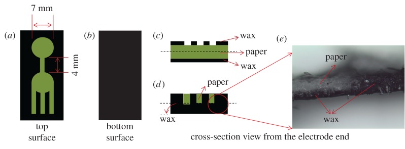
Figure 2.
(a) A schematic illustrating the top surface of the wax-printed paper. The reaction zone and the entry port have diameters of 7 mm, while the interconnecting channel measures 4 mm in length and 1.5 mm in width. (b) The bottom surface of the paper is entirely wax printed to render it hydrophobic and to prevent leakage. (c,d) Cross-sections of the device from the electrode-end before and after heating, respectively. Note that the wax on both sides has melted and impregnated into the paper as evidenced by the photograph in (e). Paper regions are coloured green for easy visualization.

