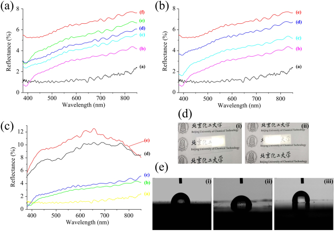
Figure 4.
(a) Optical reflectance spectra of AR sub-wavelength structured samples. (Curves a-e represent imprinting forces of 350, 250, 200, 150 and 100 N; curve f represents the flat UV-curable resin coated PC substrate); (b) Optical reflectance spectra of samples with different parameters (imprinting force and resin viscosity). (Curves a-d represent parameters of (a) 350 N, 100 cps; (b) 250 N, 100 cps; (c) 250 N, 400 cps; and (d) 250 N, 800 cps, curve e represents the flat UV-curable resin coated PC substrate); (c) Measured angle-dependent reflectance at different incidence angles. (Curves a-e represent incidence angles of 0°, 30°, 50°, 60°, and 75°); (d) Photographs of half side AR sub-wavelength structured samples exposed to conventional room illumination. Characters are visible only under the (i) left and (ii) right half, since they are cover with AR structures; (e) Water contact angles of (i) bare PC substrate, (ii) flat UV-curable resin coated PC substrate, and (iii) AR sub-wavelength structured sample fabricated with an imprinting force of 350 N and a resin viscosity of 100 cps (sample 4 in Table 1).

