
Figure 5. Gating mechanism of MmTPC1.
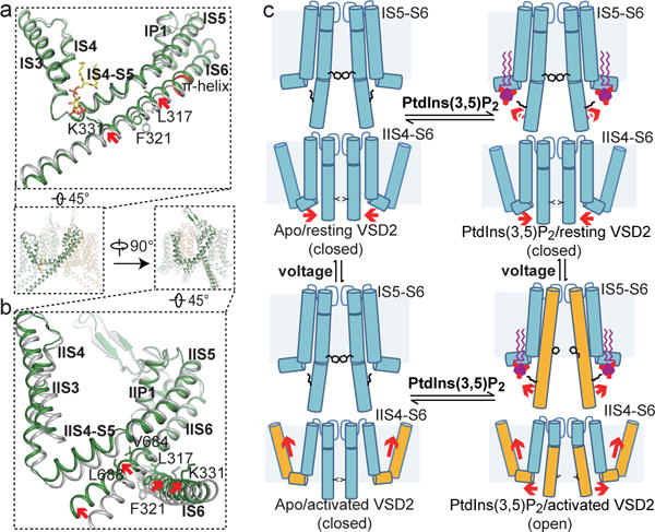
a and b, Structural comparison between the apo closed (grey) and PtdIns(3,5)P2-bound open (green) MmTPC1 with zoomed-in views of the IS3-S6 (a) and IIS3-S6 (b) regions. Arrows indicate the S6 movements. Key gating residues are shown as sticks. IS6 contains a 5-residue π-helix (colored in red). c, Working model for voltage-dependent PtdIns(3,5)P2 activation of MmTPC1. Red arrows mark the direction of the driving force.