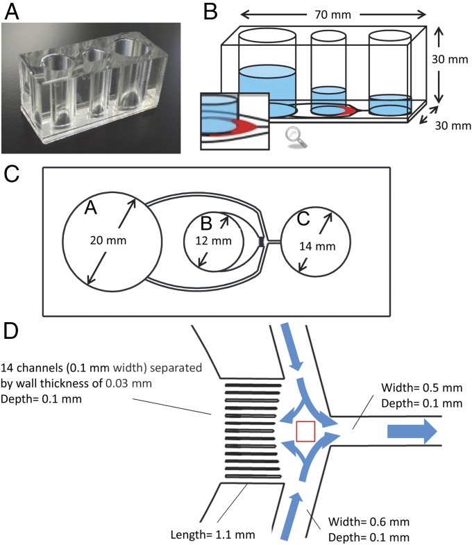
Fig. 1.
Photograph and schematic illustration of the DMSS device. (A) Photograph of the device composed of PDMS and glass. (B) Illustration of microchannels and chambers A, B, and C (sorting medium, semen seeding, and collection, respectively). The crescent shape diffuser is shown in red. (C) Microchannel design and geometry from the bottom view of the device. The medium flowing out from chamber A is supplied into chamber B and C. Motile sperm are sorted from frozen–thawed semen in chamber B and accumulated in chamber C; thus, motile sperms are collected from chamber C. (D) Magnified illustration of the microchannel network showing the junction area as indicated by the red square. The 14 microchannels separated by walls form laminar flow distribution that flows continuously into crescent-shaped diffuser enabling more motile spermatozoa to swim into this zone, pass through, and travel the distance along the multiple microchannels.

