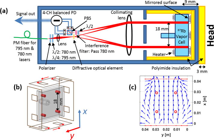
Figure 1.

a) The OPM sensor’s schematic, b) a drawing of the on-sensor coils as they are positioned relative to the vapor cell (the red cylinders indicate the volume over which the magnetic field is measured, and the red arrows indicate the coils’ current flow to generate an x-axis field.), and c) the simulated magnetic field generated by the on-sensor coils. PBS: polarizing beam splitter; PM: polarization maintaining, PD: photodiode, λ/2: half wave plate, λ/4: quarter wave plate.
