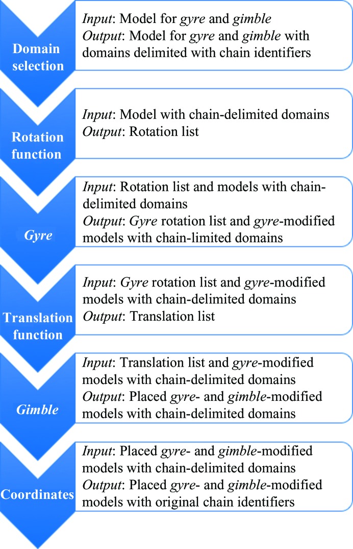
Figure 2.
Flow diagram for gyre and gimble refinement as implemented in phenix.gyre_and_gimble. Gyre refinement takes the rotation list from a standard Phaser rotation function and, for each orientation, refines the orientation and relative positions of the domains. One coordinate file is output for each input orientation. The corresponding rotation list output from gyre refinement has all of the orientation angles set to zero, with the coordinates to which each orientation refers being different. This is in contrast to a standard rotation list, where the coordinates for each trial rotation are the same and it is the orientations that differ. After the translation function, gimble refinement modifies the positions and orientations of the fragments by refinement against the LLGI target, and the final oriented, placed and perturbed coordinates are written out. The phenix.gyre_and_gimble implementation optimizes the placement of domains for a single copy of a model in the asymmetric unit. Other models can be placed in the asymmetric unit using standard molecular replacement or, if conformational change is suspected in further components, further gyre and gimble procedures.

