
Figure 14.
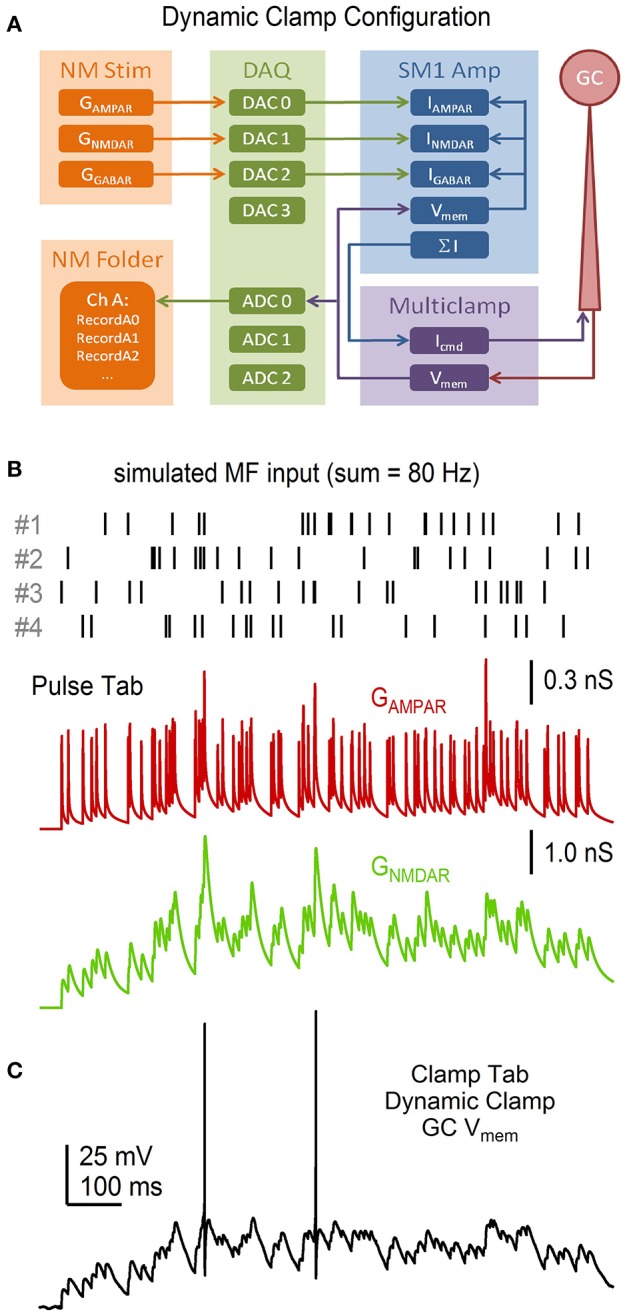
Dynamic-clamp acquisition using simulated synaptic conductance trains. NeuroMatic Pulse tab R·P plasticity models were used to simulate 4 statistically different MF inputs with mean spike rate f. The 4 MF inputs were summed together and injected into a real GC via dynamic clamp. (A) Flowchart of the dynamic-clamp experiment. NeuroMatic sent precomputed GAMPAR, GNMDAR and GGABAR waves to 3 DAC channels of a DAQ device, which were connected to the appropriate input channels of a dynamic-clamp SM1 amplifier. In real time, the SM1 amplifier converted the conductances to currents using Vmem of the GC, via the Multiclamp amplifier, and preset reversal potentials, i.e., I = G·(Vmem – Vrev). The sum of the 3 currents was sent to the command input of the Multiclamp amplifier (Icmd). The Multiclamp amplifier recorded the GC Vmem response to Icmd and sent Vmem to an ADC channel of the DAQ device, which was read by NeuroMatic. (B) Synaptic event times for 4 simulated MF inputs (top) computed by the Pulse tab. Event times had random Poisson intervals >1 ms with f = 20 Hz. The GAMPAR train (middle) was computed from the 4 event trains, where each train had its own R·P plasticity model as described in Figure 13, and the resulting 4 conductance trains were summed together. The GNMDAR train (bottom; before Mg2+ block) was computed in the same way, but included facilitation. Parameters for the GAMPAR and GNMDAR trains are as reported in Billings et al. (2014). (C) GC Vmem in response to injection of the GAMPAR and GNMDAR trains in (B) via dynamic clamp. The injection included a tonic GGABAR of 0.27 nS. Reversal potentials of the AMPAR, NMDAR and GABAR channels were 0, 0 and −75 mV, respectively. The resting potential of this recording was −75 mV. GC experimental details: cerebellar slice from P24 rat, Ra = 26.7 MΩ, Cmem = 2.6 pF.