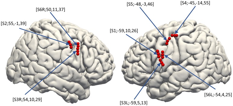
Figure 2.
Electrode distribution. The normalized electrode contacts (Red dots) extracted from post-implantation computed tomography from all subjects were overlaid on a normalized brain within FreeSurfer software ver. 6.0.0 (https://surfer.nmr.mgh.harvard.edu/). Note that each set of three electrodes represents one hybrid electrode. Pre-operative MRI was semi-automatically registered to post-operatively scanned computed tomography to determine electrode positions based on a normalized mutual information method using Dr.View (Asahi Kasei, Tokyo, Japan). Both the pre-operative MRI and the registered post-operative computed tomography were then normalized to Montreal Neurological Institute coordinates via linear scale adjustment using SPM8 (http://www.fil.ion.ucl.ac.uk/spm/software/spm8/, Update Revision Number 6313), and then the coordinates for each electrode were extracted.

