
Figure 2.
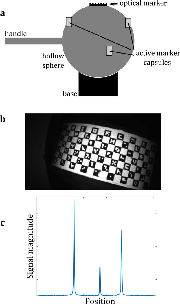
(a) The calibration tool, comprising both an optical marker and three wireless active markers, combined in a rigid arrangement. All markers are fixed to a hollow plastic sphere (10 cm diameter), which can be moved as a rigid body (rotations and translations only; no scaling or shearing). The calibration tool is placed at approximately the scanner isocenter. Rotations in all three directions are applied manually using the plastic handle. (b) A video frame of the calibration tool, used to calculate the pose of the tool in camera coordinates (c) MR projection data of the active markers on the tool, used to calculate the pose of the tool in scanner coordinates.