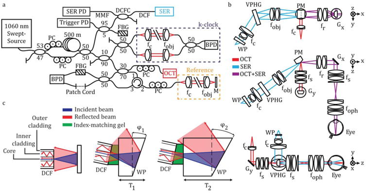
Figure 1.

SECTR system schematic. (a) A 1060 nm swept-laser source was optically buffered and split between OCT and SER arms. One output of the buffering stage was split for OCT and k-clock, and the path was subsequently split between a reflective reference and sample arms. The second output of the buffering stage coupled SER illumination to a DCF coupler for single-mode illumination and multimode detection through the core and inner-cladding of the DCF, respectively. FBGs in the SER and OCT arms were used to generate a wavelength-specific trigger and remove phase-noise from laser sweep jitter, respectively. (b) Orthogonal cross-sections showing SECTR beam paths and imaging optics (OCT, red; SER, blue; shared OCT+SER, purple). OCT and SER paths were combined by a prism mirror and shared a galvanometer scanner (Gx: OCT fast-axis and SER scan axis). (c) Schematics showing back-coupling of end-face reflections in a DCF from the fiber-air interface and a downstream air-glass interface (left). Both reflections were reduced by coupling the DCF to a wedge-prism (WP) with thickness, T1, and wedge angle, φ1, (middle) and were minimized for T2 and φ2 (right). BPD, balanced photodiode; f, collimating, objective, ophthalmic, relay, and scan lenses; Gx, y, galvanometer scanners; M, mirror; MMF, multimode fiber; PC, polarization controller; PD, photodiode; PM, prism mirror; VPHG, grating.
