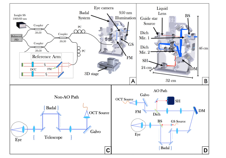
Fig. 1.
Overview of the compact swept source (SS)-OCT prototype system. (A) OCT interferometer configuration and beam propagation in the large field of view (FoV) imaging mode. PC polarization controller, PD photodiode, GS galvanometer scanner, FM flip mirror, DCC dispersion compensation component. (B) Scheme of the sample arm optics showing the beam propagation in AO imaging mode. The blue line shows the optical path of the OCT beam, the red line represents the light path of a guide star used for wavefront sensing. The dimensions of the sample arm housing are also specified. (C) Detailed beam propagation for the non-AO imaging mode. (D) Detailed beam propagation for the AO-imaging mode. Dich Mir. 1,2 dichroic mirrors, BS beam splitter, DM deformable mirror, SH Shack Hartmann wavefront sensor.

