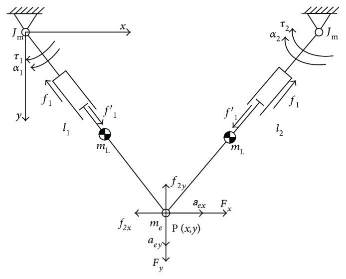
Figure 5.

Robotic dynamics of the mechanism. In this diagram, τ1 and τ2 denote the motor torques; f1 and f1′ are the friction in the prismatic joint; f2x and f2y denote the friction between the end-effector and platform; Fx and Fy denote the interactive force between patients and the robot; mL, me, and Jm denote the inertia of the link, end-effector, and the moment of inertia of the motor shaft, respectively; α and a represent the acceleration of the joints and end-effector, respectively.
