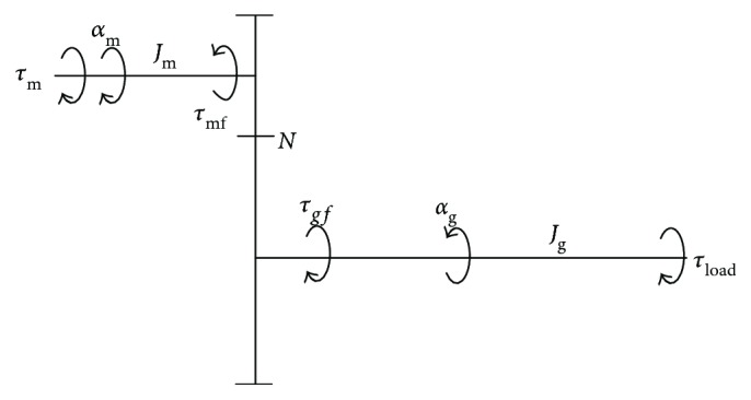
Figure 6.

Dynamics of the motor-gear system. Jm and Jg denote the moments of inertia of the motor and gear shafts, respectively; τmf, τgf and αm, αg are the friction torques and angular accelerations of the two shafts, respectively; τm and τload represent the motor and load torques, respectively; N is the gear ratio.
