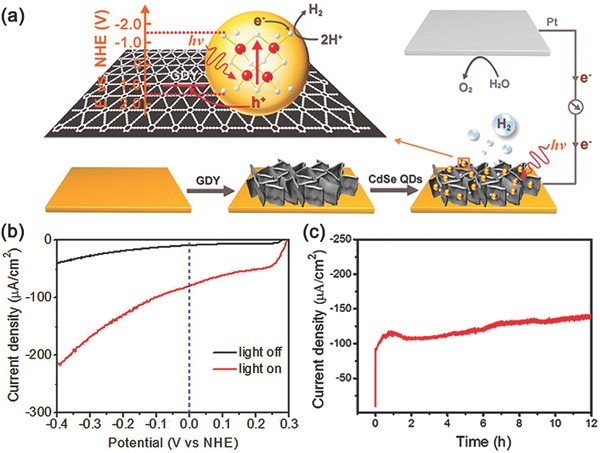
Figure 17.

a) Schematic diagram of the PEC cell, consisting of the assembled CdSe QDs/GDY photocathode, Pt wire as counter electrode, and corresponding interfacial migration process of the photogenerated excitons. b) LSV scanning from 0.3 to −0.4 V at 2 mV s−1 with light off (black trace) and on (red trace) for CdSe QDs/GDY photocathode. c) Controlled potential electrolysis of CdSe QDs/GDY photocathode during 12 h test. Reproduced with permission.186 Copyright 2016, American Chemical Society.
