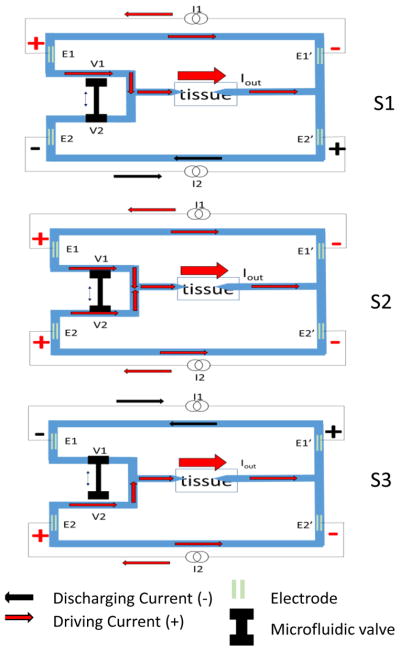
Figure 3.
Conceptual three states of SDCS3 are shown. The system cycles from S1 to S2 to S3, and then back from S3 to S2 to S1 continually. During S1, I1 drives the current through the tissue via E1 and E1′ and I2 discharges E2, E2′ electrodes. During S3, I2 drives the current through the tissue and I1 discharges its electrodes. The tandem microfluidic valve is composed of two ports V1 and V2. This V1 and V2 change states during S2 and this transition results in initial opening of both valves and then closing the next one in sequence. The arrows pointing at the tissue represent microcatheter tubes filled with an electrolyte gel to allow ionic current flow to the neural targets.

