Abstract
We introduce a simple method to characterize the topological charge associated with the orbital angular momentum of a m-order elliptic light beam. This method consists in the observation of the far field pattern of the beam carrying orbital angular momentum, diffracted from a triangular aperture. We show numerically and experimentally, for Mathieu, Ince–Gaussian, and vortex Hermite–Gaussian beams, that only isosceles triangular apertures allow us to determine in a precise and direct way, the magnitude m of the order and the number and sign of unitary topological charges of isolated vortices inside the core of these beams.
Introduction
Light beams possessing orbital angular momentum (OAM) have been extensively studied since its first demonstration in 19921,2. Laguerre-Gauss3 and Bessel beams4 are examples of beams carrying OAM. They can be decomposed in terms of orthogonal components, and it is possible to construct a geometric representation equivalent to the Poincaré sphere for the polarization5. These beams have found applications in optical tweezers6, singular optical lattice generation7, atom traps8, transfer of OAM to microparticles9, nanostructures and atoms10, and for shaping Bose–Einstein condensates11. Another important application is the preparation of photons entangled in their orbital angular momentum (OAM) degree of freedom2,12, which are candidates for implementing high performance quantum communication13.
Elliptical vortex beams (EVBs) have also received considerable attention in recent years14–18. This type of beam has an elliptical symmetry which is stable on propagation and it is also promising for all previous applications of circular OAM beams, for instance, the EVBs have been applied in optical trapping and manipulation of particles19,20, quantum information21,22, and beam shaping in nonlinear media23,24. Several EVBs were investigated earlier, including Mathieu14,15, helical Ince–Gaussian (HIG)16, vortex Hermite–Gaussian (VHG) beams17, and elliptic perfect optical vortices18. Other works have investigated simple ways of producing EVBs25,26. However, the diffraction of these beams by apertures has not been extensively investigated, except a method for measuring the orbital angular momentum of elliptical vortex beams by using a slit hexagon aperture27.
We contribute to this type of study, by showing that the order m of an EVB can be determined by inspection of the diffraction pattern from an isosceles triangular aperture. It is known that the topological charge (TC) of circular beams can be determined by interferometric28–30 and diffractive31–37 methods. For Laguerre-Gaussian and Bessel beams, the sign and magnitude of the topological charge can be determined by diffraction through an equilateral triangular aperture38. We extend this method for EVBs by changing from an equilateral to an isosceles triangular aperture.
We demonstrate that the order m and the beam wavefront helicity sign can be obtained from the diffraction pattern in an unambiguous and direct way up to m = 10. The procedure is only reliable for isosceles triangular apertures. We discuss a practical method to design the most appropriated triangular aperture for this task.
Results
The theoretical approach for this diffraction problem consists in calculating the far field pattern by a triangular aperture. In order to do that, we use the Fraunhofer integral given by39
| 1 |
where E(x, y, z) gives the electric field amplitude at the transverse position with coordinates (x, y) in the plane situated at a distance z from the diffraction screen. λ is the wavelength in the vacuum, k is the wavevector and E0 is a constant.
As we are interested in the transverse intensity distributions at a fixed plane placed at the position z = z0, far enough from the aperture, we can use the scale transformations Kx = k.x/z0, Ky = k.y/z0, and omit the term outside the integral. Thus, the Fraunhofer integral becomes a Fourier transform,
| 2 |
where E(x′, y′, 0) is the product between the incident field and the aperture function. Due to the elliptical symmetry of the EVBs, the appropriated aperture must have an isosceles triangular shape and it should be placed in the beam as described in more detail below. The longer axis of the aperture should lie along the longer axis of the beam. For integer and circular OAM beams, the integral in Eq. (2) for the triangular aperture can be analytically evaluated40. However, for EVBs, analytical solutions were not yet derived. Therefore, we will solve these integrals numerically.
In Fig. 1 we show in red, an isosceles triangle representing the aperture inscribed in an ellipse representing the shape of the beam. In order to design the optimal triangle, we need to measure the intensity transverse profile of the beam at the position where the aperture will be placed. From the intensity pattern, we obtain the dimensions of the semi-minor axis a1 and semi-major axis b1, which are the distances from the center to the intensity global maxima in the x and y directions, respectively. This provides us with the equation for the ellipse shown in Fig. 1, with eccentricity . In order to obtain the coordinates (−x, y) and (x, y) for the vertices of the triangle, we apply the transformation and to obtain and . This procedure was developed in order to maximize the visibility of the diffraction features that contain the information about the topological charge, as a function of the relative sizes of beam and aperture. When the elliptical beam tends to a circular one, the optimal aperture tends to the equilateral triangle.
Figure 1.
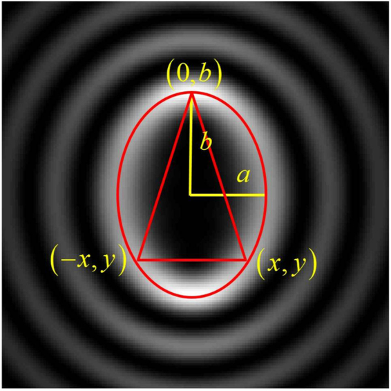
Geometry of the edges of an isosceles triangular aperture inscribed in an ellipse matching the global maxima of the intensity pattern of a Mathieu beam with m = 5 and q = 6.
In this work, we approach three types of elliptical beams. The helical Mathieu beams are solutions of the Helmholtz equation in the elliptic cylindrical coordinates and can be constructed from a linear combination of even and odd Mathieu functions as14
| 3 |
where ξ and η are the radial and angular variables in the elliptical coordinates, Jem(·) and Jom(·) represent the mth-order even and odd radial Mathieu functions and cem(·), sem(·) correspond to the mth-order even and odd angular Mathieu functions. Cm and Sm are the normalization coefficients and q is a parameter that characterizes the ellipticity of the beam. The sign in Eq. (3) defines the rotating direction of the wavefront.
The HIG modes are solutions of the paraxial wave equation (PWE), also in the elliptic cylindrical coordinates, and can be expressed as a superposition of even and odd Ince–Gaussian modes (IGMs)16,
| 4 |
where ξ and η are the radial and the angular elliptic variables, respectively, and ε is the ellipticity parameter. The parameter p is related to the number of rings which is given by the relation , and m gives the overall topological charge. and are even and odd IGMs, respectively.
The VHG beams are formed from a superposition of n + 1 generalized Hermite–Gaussian beams41, which are solutions of the PWE in Cartesian coordinates, and their complex amplitudes are given by17,
| 5 |
where x and y are the Cartesian coordinates, m is the order of the beam, a is a real constant that controls the beam ellipticity, Hn(·) is the Hermite polynomial, and wx and wy are the Gaussian beam waist radii.
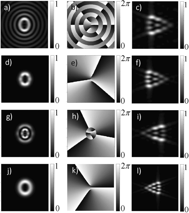
Figure 2 shows the theoretical transverse intensity (left column), phase (center column), and Fraunhofer diffraction patterns (right column) for EVBs. Figure 2(a)–(c) correspond to a Mathieu beam with m = 3 and q = 2, Fig. 2(d)–(f) correspond to a HIG beam with m = 3, p = 3 and ε = 1, Fig. 2(g)–(i) correspond to a HIG beam with m = 3, p = 5 and ε = 1, and Fig. 2(j)–(l) correspond to a VHG beam with m = 3 and a = 0.80. For all of these modes, the sign of m does not determine the helicity, or the sense of rotation of the wavefront. For Mathieu and HIG beams the helicity depends on the sign of the imaginary term in Eqs (3) and (4), while for VHG beams it depends if the parameter a in Eq. (5) is bigger or smaller than 1. In Fig. 2(e) and (h), the effect of changing the sign in Eq. (4) is illustrated. In Fig. 2(e) the sense of increasing phase is clockwise, while in Fig. 2(h) it is counterclockwise. The phase distribution maps in Fig. 2(b),(e),(h) and (k), also illustrate the fact that the mth-order EVB with nonzero eccentricity contains m in-line vortices, each one with unitary topological charge of the same sign such that the modulus of the total charge is m.
Figure 2.
Calculated intensities (left column), phase (center column), and Fraunhofer diffraction patterns (right column) for EVBs. From the top to the bottom, the first row: Mathieu beam with m = 3 and q = 2; second row: HIG beam with m = 3, p = 3 and ε = 1; third row: HIG beam with m = 3, p = 5 and ε = 1; fourth row: VHG beam with m = 3 and a = 0.80. From second to third rows we see the effect of changing the sign in Eq. (4).
The patterns 2(c), 2(f), 2(i), and 2(l), resulting from diffraction through an isosceles triangular aperture allow us to determine m and the sign of the unitary vortices at the beam core. The number of bright spots is directly related to m, and the sign is given by the orientation of the pattern. According to the simulations, a safe region for the method to work is in the range of 0 < e ≤ 0.8 and m ≤ 10. Out of these limits the patterns are not truncated and we cannot properly count the number of spots anymore.
In Fig. 3 we show the numerically computed diffraction patterns for the mth-order input Mathieu beams. Comparing the diffraction patterns for different values of m, it is possible to establish a rule to determine the order of the beams, in the same way as for the HIG and VHG beams. We can observe that the value of m is directly related to the first order external diffraction lobes (maxima) formed on the sides of the triangle. The total charge is given by m = N - 1, where N is the number of lobes on anyone of the sides of the triangle. This is valid for all EVBs studied here.
Figure 3.
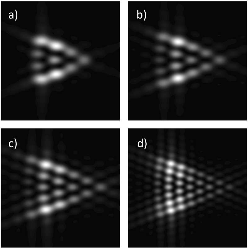
Fraunhofer patterns of Mathieu beams diffracted by a triangular aperture. (a) m = 3, q = 2, (b) m = 4, q = 3, (c) m = 5, q = 4, and (d) m = 7, q = 7. Notice that each side has m + 1 bright spots.
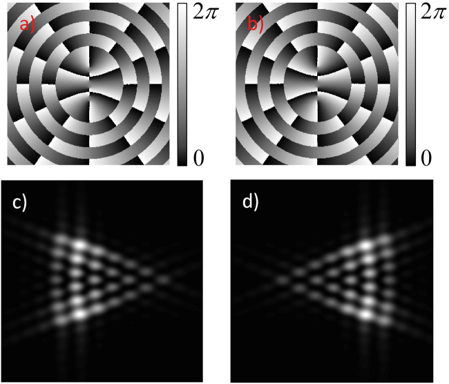
Figure 4 illustrates the effect of changing the sign of the imaginary part in Eq. (3) for a Mathieu beam, with clockwise rotation (plus sign in Eq. (3)), in Fig. 4(a) and (c), and counterclockwise rotation (minus sign in Eq. (3)), in Fig. 4(b) and (d).
Figure 4.
Effect of changing the sign in Eq. 3 in the Fraunhofer diffraction patterns. (a) and (c) m = 6, q = 6 for plus sign (clockwise increasing phase); (b) and (d) m = 6, q = 6 for minus sign (counterclockwise increasing phase).
So far, we have shown numerically that the diffraction pattern through an isosceles triangular aperture determines the total topological charge m, and the helicity of Mathieu, HIG and VHG beams in a clear and unambiguous way. In order to obtain this result, we have analyzed other geometries for the diffraction aperture like a lozenge for instance, but our studies demonstrated that the isosceles triangle is the most appropriated geometry. This is similar to what happens for circular beams, for which other geometries like a square aperture, for instance, can determine the modulus of the topological charge but not the sign25. In this last case, only the equilateral triangle can provide the complete information about m and its sign38.
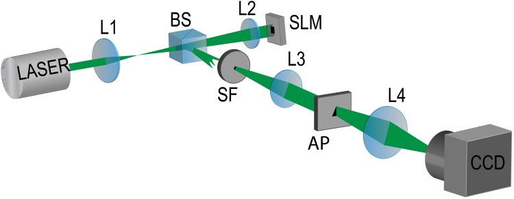
We have performed an experiment, in order to confirm our numerical results. Figure 5 shows the sketch of the experimental setup, which is described in detail in section “Methods”. We have diffracted Mathieu, HIG and VHG beams through an isosceles triangular aperture, and demonstrated the validity of our method to determine the order m of EVB beams.
Figure 5.
Experimental Setup: L1, L2, L3 and L4 are lenses, BS is a 50/50 beam splitter, SLM is a spatial light modulator, SF is a spatial filter, AP is the triangular aperture and CCD is a camera.
In Fig. 6, we show the experimental results. The triangular structures are the diffraction patterns and each side of the triangles has m + 1 bright spots as theoretically predicted. These results confirm our numerical results and demonstrate the use of diffraction patterns by triangular aperture to determine the order of EVBs. They also confirm that the information about the helicity of the wavefront is given by the orientation of the triangular pattern. Different from the traditional circular modes, e.g. Laguerre Gauss and Bessel beams38, the sense of wavefront rotation is not determined by the sign of m. We have found a very good agreement between theory and experiment.
Figure 6.
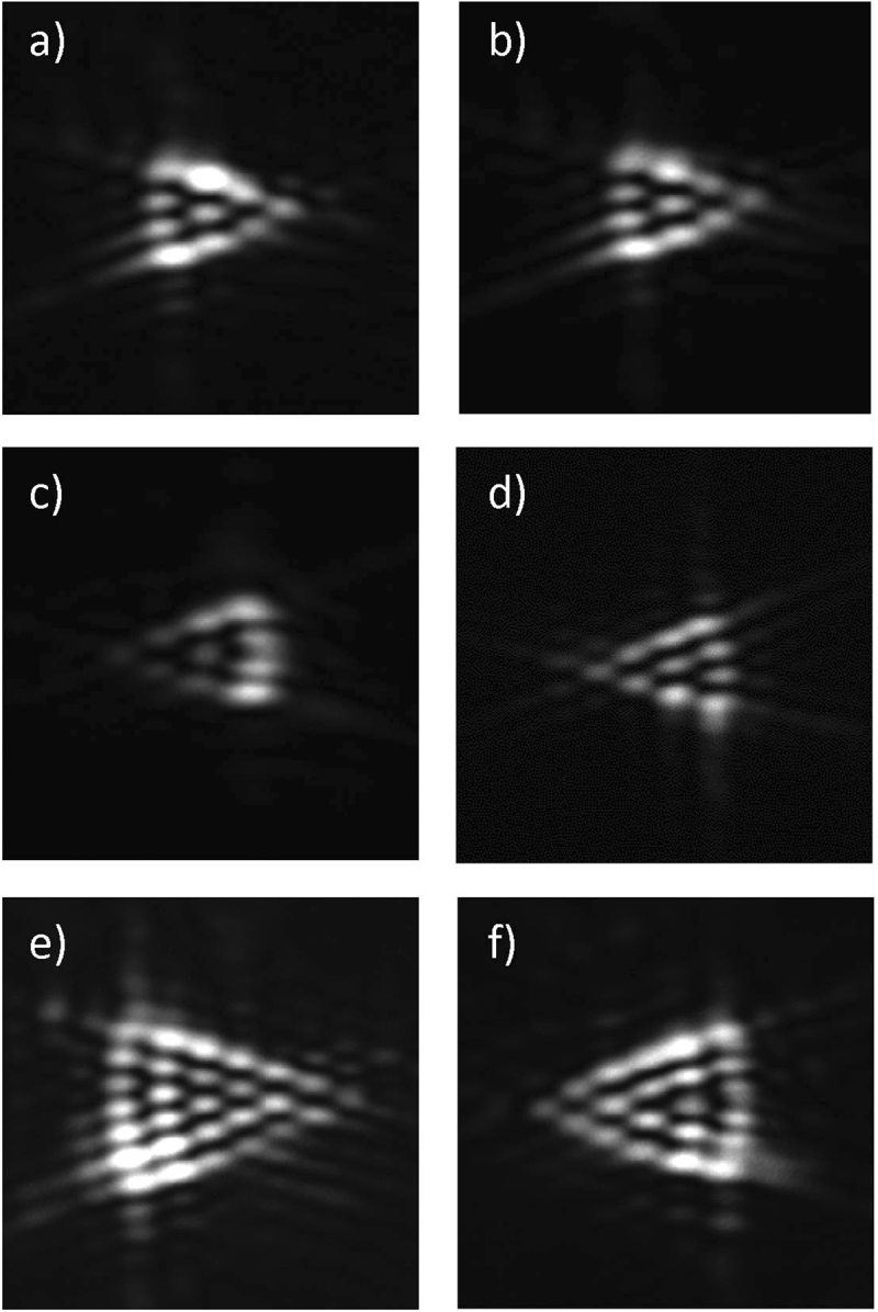
Experimental results for the intensity distribution of the diffraction patterns for EVBs: (a) Mathieu beam with m = 3 and q = 2, (b) HIG beam with m = 3, p = 3 and ε = 1, (c) HIG beam with m = 3, p = 5 and ε = 1, (d) VHG beam with m = 3 and a = 0.80, (e) Mathieu beam with m = 6 and q = 6, and (f) HIG beam with m = 5, p = 9 and ε = 1.
Conclusion
In summary, we have numerically and experimentally demonstrated a technique that allows us to determine the order of an EVB in an unambiguous way. We have also presented a recipe to design the optimal triangular aperture for this measurement. This non–interferometric technique requires only simple measurements of intensity patterns. The value of m is determined by counting the number of lobes in anyone of the sides of the triangular diffraction pattern. The sense of wavefront rotation can also be determined by the orientation of the diffraction pattern.
Methods
The experimental setup is shown in Fig. 5. Different orders and types of EVBs are generated from an initial Gaussian mode of an Argon Laser operating at 514 nm. The beam is expanded by a factor of about 17, using lenses L1, with focal length f1 = 30 mm, and L2, with focal length f2 = 500 mm. The expanded beam illuminates a computer-generated hologram42 displayed in a spatial light modulator (SLM) (Hamamatsu Model X10468-01). The 50/50 beam splitter (BS) in between L1 and L2 is used to allow normal incidence in the SLM. For each type of EVB there is a corresponding type of hologram in the SLM. The reflected beam from the SLM is focused by lens L2 in the plane of the spatial filter (SF) after reflection by the BS. The spatial filtering selects the desired diffraction order from the SLM. Lens L3, with focal length f3 = 300 mm, collimates the beam again, which is incident on the isosceles triangular aperture (AP). It is mounted in a xyz translation stage for precise alignment with respect to the light beam. Finally, lens L4, with focal length f4 = 200 mm, is used to implement the optical Fourier Transform of the field in the aperture plane onto the CCD detection plane. This is the physical realization of the integration in Eq. (2). The transverse intensity patterns corresponding to the Fraunhofer diffraction are registered.
Acknowledgements
This work was supported by Fundação de Amparo à Pesquisa do Estado de Alagoas (FAPEAL) (Proc. n° 60030.1029/2016 – Edital Universal 4/2016 – Programa estadual de auxílio à pesquisa - APQ). Coordenação de Aperfeiçoamento de Pessoal de Nível Superior (CAPES); Conselho Nacional de Desenvolvimento Científico e Tecnológico (CNPq); Instituto Nacional de Ciência e Tecnologia de Informação Quântica (INCT-IQ). W. C. Soares thanks PNPD/Capes – UFSC program.
Author Contributions
W.C.S. proposed the idea, worked out the theory. L.A.M. and A.J.J.S. were responsible for the experiments. All authors contributed to the data analysis and interpretation of the results. A.J.J.S., P.H.S.R., S.C.C. and W.C.S. wrote the manuscript.
Competing Interests
The authors declare no competing interests.
Footnotes
Publisher's note: Springer Nature remains neutral with regard to jurisdictional claims in published maps and institutional affiliations.
References
- 1.Allen, L., Barnett, S. M. & Padgett, M. J. Optical angular momentum (Institute of Physics Pub., 2003).
- 2.Padgett MJ. Orbital angular momentum 25 years on. Opt. Express. 2017;25:11265–11274. doi: 10.1364/OE.25.011265. [DOI] [PubMed] [Google Scholar]
- 3.Allen L, Beijersbergen MW, Spreeuw RJC, Woerdman JP. Orbital angular momentum of light and the transformation of Laguerre-Gaussian laser modes. Phys. Rev. A. 1992;45:8185–8189. doi: 10.1103/PhysRevA.45.8185. [DOI] [PubMed] [Google Scholar]
- 4.Volke-Sepulveda K, Garcés-Chávez V, Chávez-Cerda S, Arlt J, Dholakia K. Orbital angular momentum of a high-order Bessel light beam. J. Opt. B.-Quantum S. O. 2002;4:S82. doi: 10.1088/1464-4266/4/2/373. [DOI] [Google Scholar]
- 5.Soares WC, Caetano DP, Hickmann JM. Hermite-Bessel beams and the geometrical representation of nondiffracting beams with orbital angular momentum. Opt. Express. 2006;14:4577–4582. doi: 10.1364/OE.14.004577. [DOI] [PubMed] [Google Scholar]
- 6.Curtis JE, Koss BA, Grier DG. Dynamic holographic optical tweezers. Opt. Commun. 2002;207:169–175. doi: 10.1016/S0030-4018(02)01524-9. [DOI] [Google Scholar]
- 7.Soares WC, Moura AL, Canabarro AA, Lima E, Hickmann JM. Singular optical lattice generation using light beams with orbital angular momentum. Opt. Lett. 2015;40:5129–5131. doi: 10.1364/OL.40.005129. [DOI] [PubMed] [Google Scholar]
- 8.Power WL, Allen L, Babiker M, Lembessis VE. Atomic motion in light beams possessing orbital angular momentum. Phys. Rev. A. 1995;52:479–488. doi: 10.1103/PhysRevA.52.479. [DOI] [PubMed] [Google Scholar]
- 9.Gahagan KT, Swartzlander GA. Simultaneous trapping of low-index and high-index microparticles observed with an optical-vortex trap. J. Opt. Soc. Am. B. 1999;16:533–537. doi: 10.1364/JOSAB.16.000533. [DOI] [Google Scholar]
- 10.Marago OM, Jones PH, Gucciardi PG, Volpe G, Ferrari AC. Optical trapping and manipulation of nanostructures. Nat. Nano. 2013;8:807–819. doi: 10.1038/nnano.2013.208. [DOI] [PubMed] [Google Scholar]
- 11.Feder DL, Clark CW. Superfluid-to-Solid Crossover in a Rotating Bose-Einstein Condensate. Phys. Rev. Lett. 2001;87:190401. doi: 10.1103/PhysRevLett.87.190401. [DOI] [PubMed] [Google Scholar]
- 12.Mair A, Vaziri A, Weihs G, Zeilinger A. Entanglement of the orbital angular momentum states of photons. Nature. 2001;412:313–316. doi: 10.1038/35085529. [DOI] [PubMed] [Google Scholar]
- 13.Torres JP, Deyanova Y, Torner L, Molina-Terriza G. Preparation of engineered two-photon entangled states for multidimensional quantum information. Phys. Rev. A. 2003;67:052313. doi: 10.1103/PhysRevA.67.052313. [DOI] [Google Scholar]
- 14.Chávez-Cerda S, Gutiérrez-Vega JC, New GHC. Elliptic vortices of electromagnetic wave fields. Opt. Lett. 2001;26:1803–1805. doi: 10.1364/OL.26.001803. [DOI] [PubMed] [Google Scholar]
- 15.Chávez-Cerda S, et al. Holographic generation and orbital angular momentum of high-order Mathieu beams. J. Opt. B.-Quantum S. O. 2002;4:S52. doi: 10.1088/1464-4266/4/2/368. [DOI] [Google Scholar]
- 16.Bandres MA, Gutiérrez-Vega JC. Ince–Gaussian modes of the paraxial wave equation and stable resonators. J. Opt. Soc. Am. A. 2004;21:873–880. doi: 10.1364/JOSAA.21.000873. [DOI] [PubMed] [Google Scholar]
- 17.Kotlyar VV, Kovalev AA, Porfirev AP. Vortex Hermite–Gaussian laser beams. Opt. Lett. 2015;40:701–704. doi: 10.1364/OL.40.000701. [DOI] [PubMed] [Google Scholar]
- 18.Kotlyar VV, Kovalev AA, Porfirev AP. Elliptic perfect optical vortices. Optik. 2018;156:49–59. doi: 10.1016/j.ijleo.2017.10.144. [DOI] [Google Scholar]
- 19.López-Mariscal C, Gutiérrez-Veja JC, Milne G, Dholakia K. Orbital angular momentum transfer in helical Mathieu beams. Opt. Express. 2006;14:4182–4187. doi: 10.1364/OE.14.004182. [DOI] [PubMed] [Google Scholar]
- 20.Alpmann C, Bowman R, Woerdemann M, Padgett M, Denz C. Mathieu beams as versatile light moulds for 3D micro particle assemblies. Opt. Express. 2010;18:26084–26091. doi: 10.1364/OE.18.026084. [DOI] [PubMed] [Google Scholar]
- 21.Krenn M, et al. Entangled singularity patterns of photons in Ince-Gauss modes. Phys. Rev. A. 2013;87:012326. doi: 10.1103/PhysRevA.87.012326. [DOI] [Google Scholar]
- 22.Plick WN, Krenn M, Fickler R, Ramelow S, Zeilinger A. Quantum orbital angular momentum of elliptically-symmetric light. Phys. Rev. A. 2013;87:033806. doi: 10.1103/PhysRevA.87.033806. [DOI] [Google Scholar]
- 23.Lopez-Aguayo S, Gutiérrez-Vega JC. Elliptically modulated self-trapped singular beams in nonlocal nonlinear media: ellipticons. Opt. Express. 2007;15:18326–18338. doi: 10.1364/OE.15.018326. [DOI] [PubMed] [Google Scholar]
- 24.Deng D, Guo Q. Propagation of elliptic-Gaussian beams in strongly nonlocal nonlinear media. Phys. Rev. E. 2011;84:046604. doi: 10.1103/PhysRevE.84.046604. [DOI] [PubMed] [Google Scholar]
- 25.Kotlyar VV, et al. Elliptic Laguerre-Gaussian beams. J. Opt. Soc. Am. A. 2006;23:43–56. doi: 10.1364/JOSAA.23.000043. [DOI] [PubMed] [Google Scholar]
- 26.Kotlyar VV, Kovalev AA, Porfirev AP. “Elliptic Gaussian optical vortices,”. Phys. Rev. A. 2017;95(5):053805. doi: 10.1103/PhysRevA.95.053805. [DOI] [Google Scholar]
- 27.Liu Y, Pu J. Measuring the orbital angular momentum of elliptical vortex beams by using a slit hexagon aperture. Opt. Commun. 2011;284:2424–2429. doi: 10.1016/j.optcom.2011.01.021. [DOI] [Google Scholar]
- 28.Heckenberg NR, McDuff R, Smith CP, White AG. Generation of optical phase singularities by computer-generated holograms. Opt. Lett. 1992;17:221–223. doi: 10.1364/OL.17.000221. [DOI] [PubMed] [Google Scholar]
- 29.Harris M, Hill CA, Vaughan JM. Optical helices and spiral interference fringes. Opt. Commun. 1994;106:161–166. doi: 10.1016/0030-4018(94)90314-X. [DOI] [Google Scholar]
- 30.Harris M, Hill CA, Tapster PR, Vaughan JM. Laser modes with helical wave fronts. Phys. Rev. A. 1994;49:3119–3122. doi: 10.1103/PhysRevA.49.3119. [DOI] [PubMed] [Google Scholar]
- 31.Sztul HI, Alfano RR. Double-slit interference with Laguerre-Gaussian beams. Opt. Lett. 2006;31:999–1001. doi: 10.1364/OL.31.000999. [DOI] [PubMed] [Google Scholar]
- 32.Guo C-S, Lu L-L, Wang H-T. Characterizing topological charge of optical vortices by using an annular aperture. Opt. Lett. 2009;34:3686–3688. doi: 10.1364/OL.34.003686. [DOI] [PubMed] [Google Scholar]
- 33.Mesquita PHF, Jesus-Silva AJ, Fonseca EJS, Hickmann JM. Engineering a square truncated lattice with light’s orbital angular momentum. Opt. Express. 2011;19:20616–20621. doi: 10.1364/OE.19.020616. [DOI] [PubMed] [Google Scholar]
- 34.Silva JG, Jesus-Silva AJ, Alencar MARC, Hickmann JM, Fonseca EJS. Unveiling square and triangular optical lattices: a comparative study. Opt. Lett. 2014;39:949–952. doi: 10.1364/OL.39.000949. [DOI] [PubMed] [Google Scholar]
- 35.Zhou H, Yan S, Dong J, Zhang X. Double metal subwavelength slit arrays interference to measure the orbital angular momentum and the polarization of light. Opt. Lett. 2014;39:3173–3176. doi: 10.1364/OL.39.003173. [DOI] [PubMed] [Google Scholar]
- 36.Chen R, et al. Detecting the topological charge of optical vortex beams using a sectorial screen. Appl. Opt. 2017;56:4868–4872. doi: 10.1364/AO.56.004868. [DOI] [PubMed] [Google Scholar]
- 37.Berkhout GCG, Lavery MPJ, Courtial MPJ, Beijersbergen MW, Padgett MJ. Efficient Sorting of Orbital Angular Momentum States of Light. Phys. Rev. Lett. 2010;105:153601. doi: 10.1103/PhysRevLett.105.153601. [DOI] [PubMed] [Google Scholar]
- 38.Hickmann JM, Fonseca EJS, Soares WC, Chávez-Cerda S. Unveiling a Truncated Optical Lattice Associated with a Triangular Aperture Using Light’s Orbital Angular Momentum. Phys. Rev. Lett. 2010;105:053904. doi: 10.1103/PhysRevLett.105.053904. [DOI] [PubMed] [Google Scholar]
- 39.Goodman, J. W. Introduction to Fourier optics (McGraw-Hill, 1996).
- 40.Stahl C, Gbur G. Analytic calculation of vortex diffraction by a triangular aperture. J. Opt. Soc. Am. A. 2016;33:1175–1180. doi: 10.1364/JOSAA.33.001175. [DOI] [PubMed] [Google Scholar]
- 41.Pratesi R, Ronchi L. Generalized Gaussian beams in free space. J. Opt. Soc. Am. 1977;67:1274–1276. doi: 10.1364/JOSA.67.001274. [DOI] [Google Scholar]
- 42.Arrizón V, Ruiz U, Carrada R, González LA. Pixelated phase computer holograms for the accurate encoding of scalar complex fields. J. Opt. Soc. Am. A. 2007;24:3500–3507. doi: 10.1364/JOSAA.24.003500. [DOI] [PubMed] [Google Scholar]


