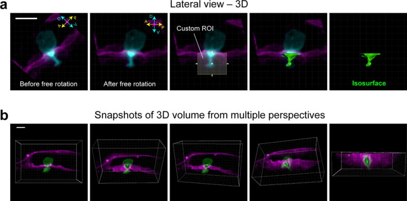
Figure 5.

Realignment by free rotation and the snapshot tool in Imaris. (a) Images show lateral view of a 3D reconstruction of the AC (cyan) as it invades through the BM (magenta). Prior to free rotation (left-most panel), the anterior-posterior (A-P) and dorsal-ventral (D-V) axes of the AC do not line up with the X- and Y-axis of the camera (white-lined grid). After free rotation, however, the AC and the camera area align. After realignment, a custom region of interest (ROI, which can only be drawn within the axes of the camera) can be used to generate an isosurface (see below, IMAGE ANALYSIS, Step 2.2) in place of the portion of the AC that has extended through BM. (b) Images of a 3D reconstruction were captured from multiple perspectives using the snapshot tool in Imaris. Scale bars represent 5 μm.
