
Figure 5.
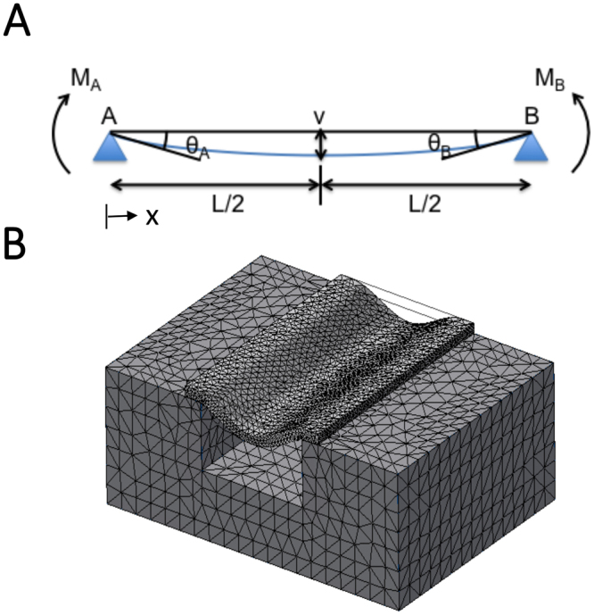
Theoretical and finite element models for membrane bending. (A) Membrane bending model modified from beam bending theory. A section of the membrane spanning the grating groove of length L is represented as a linear elastic beam with both ends (points A and B) freely supported by the adjacent grating ridges. The beam bends (blue line) under a uniformly distributed load q and the tangents to the membrane at point A and B make angles θA and θB respectively with horizontal line AB. The vertical displacement of any point x along the beam is denoted by v and is maximum when x = L/2 and θA = θB. (B) Three dimensional finite element model simulation that was used to validate the results from the theoretical model for beam bending.