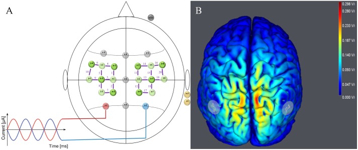
FIGURE 2.
Stimulation and neuroimaging setup. (A) tACS/EEG/fNIRS Montage for Parietal Stimulation. HD-tACS electrodes were positioned at P3 (red electrode = stimulation) and P4 (blue electrode = return). EEG was measured from five positions (F3, Fz, F4, Cz, and Pz) following the international 10–10 system (gray electrodes). fNIRS sources (light green) and detectors (dark green) are shown over the left and right motor cortices with channels (Source–Detector) depicted as purple lines (FC3–FC5, FC3–FC1, FC3–C3, C1–FC1, C1–C3, C1–CP1, C5–C3, C5–FC5, CP3–C3, CP3–CP1, FC4–FC2, FC4–FC6, FC4–C4, C2–FC2, C2–C4, C2–CP2, C6–FC6, C6–C4, CP4–CP2, und CP4–C4). (B) Simulated Electrical Field. Predicted electrical field intensities with a tACS application on P3/P4 (StartStim, Neuroelectrics, Spain). Full details regarding stimulation and brain activity measures are in the text (paragraph tACS/EEG/fNIRS approach).

