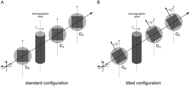
Figure 1.
Schematic laboratory GBPC-CT set-up. Subfigure (A) shows the standard Talbot-Lau configuration using three gratings with grating lines in parallel to the tomographic axis. Subfigure (B) visualizes the tilted grating setup with a rotation of the grating line orientation by α = 45° with respect to the optical axis. The sample is indicated by the cylinder centered around the tomographic axis. G0 is the source grating, G1 the phase grating, and G2 the analyzer grating. The X-ray source and the detector are not shown in this figure.

