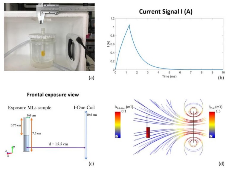
Figure 1.
(a) pulsed electromagnetic field (PEMF) exposure setup; (b) Current signal feeding the coil; (c) Model of the high-Tm MLs exposure system in the frontal exposure view; (d) Magnetic field distribution in the high-Tm MLs sample given by the magnetic field intensity of the coil (streamlines).

