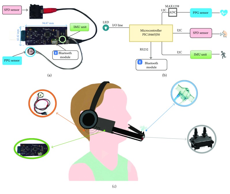
Figure 4.
(a) Detailed view of the hardware module. (b) A functional diagram of the PIC-based board. The control unit acquires and collects data from the PPG sensor (through an analog-to-digital converter), the SDP sensor for respiratory rate, and the IMU unit for body movement. Data are sent to PC by the Bluetooth module. (c) Overall system sketch. The hardware module has been embedded into a headphone. The flowmeter is positioned 10 cm ahead the mouth, and its static taps are connected to the SDP sensor. The PPG sensor is positioned on the right earlobe with an ear clip. The IMU is integrated into the hardware module in proximity with the PPG sensor.

