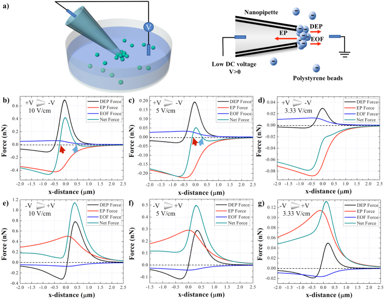
Figure 1.
(a) The schematic of the nanopipette DEP device for entrapment of the particles suspended in the solution. (b–d) DEP, EP, EOF, and the net EK forces induced on the 510 nm COOH-PS beads along the length of the pipette under positive bias of 10, 5, and 3.33 V/cm applied at the base, respectively. (e–g) DEP, EP, EOF, and the net EK forces induced on the 510 nm COOH-PS beads along the length of the pipette under negative bias of 10, 5, and 3.33 V/cm applied at the base, respectively. The part of the graph to the left of (0,0) represents the region inside of the pipette and the portion of the graph on the right of (0, 0) depicts the region outside the pipette. The red and blue arrows point out the intersection between the net EK force plot and Y=0. The ionic strength of solution is 10 mM and the diameter of the pore is 1 μm.

