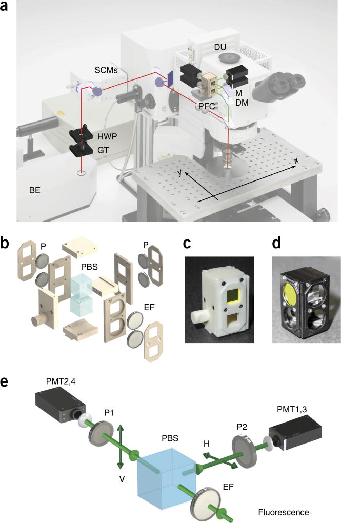
Figure 4.
Setup overview. (a) Optical path overview of the two-photon fluorescence anisotropy imaging system and the imaging reference plane orientation xy. Adapted with permission from the Olympus FV1000 microscope brochure. (b) 3D exploded view of the PFC. (c,d) Views of the final assembled 3D-printed (c) and machined (d) polarization filter cube. See Supplementary Data 2. (e) Schematic principle view of the optical path within the DU. BE, beam expander; DM, dichroic mirror; DU, detection unit; EF, emission filter; GT, Glan-Thompson polarizer; HWP, half-wave plate; M, mirror; P, polarizer; PBS, polarization beam splitter; PFC, polarization filter cube; PMT, photomultiplier; SCM, steering combining mirror.

