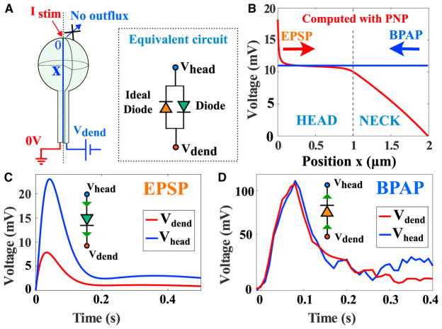
Figure 5. Summary of Dendritic Spine Electrical Responses.
(A) Schematic representation of a dendritic spine. Left: a current is injected in the head. Right: modeling the effect of the BPAP on the spine voltage. The inset is an electrical circuit representation of the spine electrical properties, composed by a diode (green) with a resistance Rneck in the direction spine to dendrite and by ideal diode in the opposite direction (orange).
(B) Electrical response of a spine (length and radius of the head are L = R = 1μm) and the radius of the neck r0 = 0.1μm, following a synaptic input (Istim = 100pA) and a BPAP, where the value depends on the voltage in the dendrite, but it is constant in the spine.
(C) Modulation of the voltage between the spine head and the dendrite: the voltage attenuation can be modeled as a diode to account for the saturation behavior (Figure 3F).
(D) Response to a BPAP showing no voltage change between the head and the dendrite, as predicted by the electro-diffusion model.

