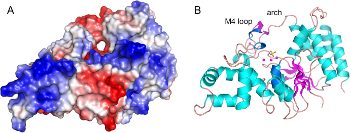
Figure 7.
Surface model of FenA highlights a hole that might accomodate a 5′ flap strand. Panel A shows a surface electrostatic model of WT FenA oriented so as to feature a through-and-through hole near the active site along the path predicted for the 5′ flap strand. Panel B shows a cartoon model of the tertiary structure in the same position used to generate the surface view. Manganese ions (magenta spheres) from the WT FenA structure, and a phosphate (stick model) imported from the D208N structure, are shown as active site landmarks in panel B.

