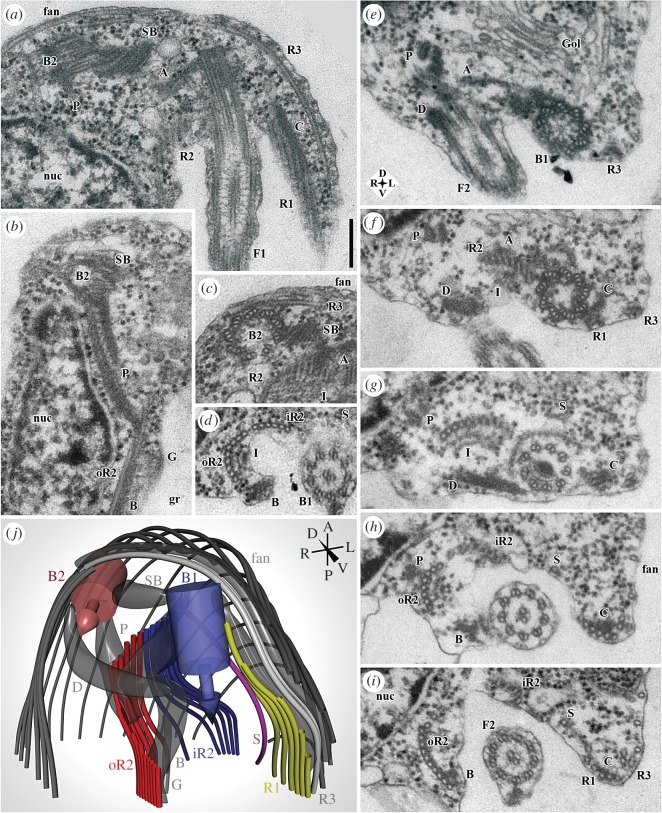
Figure 3.
Flagellar apparatus of G. okellyi, represented by transmission electron microscopy (TEM) and 3-D modelling. (a) Anterior end of cell, showing flagellar apparatus, including basal body 2 (B2) and posterior flagellum (F1), with basal body 1 forming the latter's base. (b) Detail of ‘P’ fibre, and section of inconspicuous ‘G’ fibre. (c) Transverse section through basal body 2 (B2), showing origin of microtubular root 3 (R3) and part of dorsal fan. (d) Detail of ‘I’ and ‘B’ fibres associated with microtubular root 2 (seen here just posterior to split into iR2 and oR2); note striations of ‘B’ fibre. (e–i) Series of sections through anterior portion of cell, showing origins and organization of microtubular elements supporting ventral groove (and dense fibre ‘D’ connecting the basal bodies); note compass rose for orientation. Origins of microtubular roots 1 and 2 (R1, R2) are shown in f, origin of singlet root S in g, division of R2 into iR2 and oR2 in h, origin of ‘B’ fibre in h, and connection of ‘B’ to oR2 in i. (j) Model of proximal portion of flagellar apparatus, rendered from a 21-section series; note compass for orientation. A, ‘A’ fibre; B, ‘B’ fibre; B1, basal body 1 (of posterior flagellum); B2, basal body 2 (of anterior flagellum); C, ‘C’ fibre; D, dense fibre; F1, posterior flagellum; F2, anterior flagellum; fan, dorsal fan of microtubules; G, ‘G’ fibre; Gol, Golgi apparatus; gr, groove; I, ‘I’ fibre; iR2, inner portion of microtubular root 2; nuc, nucleus; oR2, outer portion of microtubular root 2; P, ‘P’ fibre; R1–R3, microtubular roots 1–3; S, singlet microtubular root; SB, striated band. Scale bar: (a–i; in a) 200 nm.

