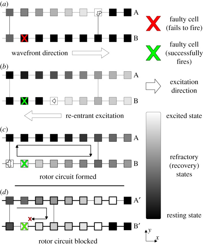
Figure 1.

The formation of a simple re-entrant circuit at the cellular level. An excited cell is shown in white and resting (excitable) cells are black. Cells shown in grey are refractory (unexcitable) for the duration of the refractory period. All cells are coupled to their nearest neighbours longitudinally—this reflects the strong coupling of cells along muscle fibres. Transverse couplings exist with probability ν—reducing ν reflects the decoupling between adjacent muscle fibres caused by fibrosis. An excitation is initiated along the left wall of the heart tissue and propagates left to right. When the excitation reaches a dysfunctional cell which fails to fire (marked by a red cross), (a) the excitation in fibre B is blocked but excitations continue in fibre A above. When a coupling between the excited and blocked strands is reached, the excited cell can send a signal propagating backwards from right to left down the blocked strand (b). If the path length of the re-excitation is sufficiently long, the re-entrant excitation can excite tissue behind the main wavefront. This signal can then move to the adjacent strands forming a continuously re-excited circuit. The simple re-entrant circuit shown here is rectangular in shape and is formed from two fibres (A & B) and a single dysfunctional cell. More complicated re-entrant circuits can consist of multiple fibres and multiple dysfunctional cells. The extract shown in (d) is for a different region of heart tissue. Here, the same mechanism as above attempts to form a re-entrant circuit. However, the circuit path length is insufficiently long such that the re-entrant excitation is blocked by the refractory cell to the left of the dysfunctional cell marked with a cross. Hence, a continuously excited circuit cannot form in this tissue segment. This behaviour explicitly links the emergence of re-entrant circuits with regions of high fibrosis (low ν). Note that the mechanism described here is for spontaneously generated circuits. The work in this paper artificially inserts circuits into the substrate such as the one shown in (c). This ensures that we can keep track of the location of all circuits in the model for analysis.
