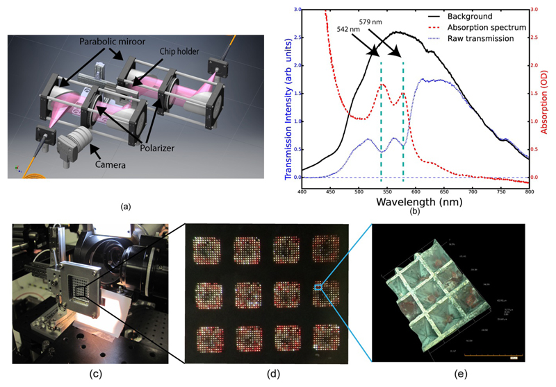
Figure 5.
(a) Schematic representation of the high-speed spectroscopy setup for mapping the loaded chip. (b) Example spectrum of a carboxy-myoglobin crystal recorded from a crystal containing feature. The characteristic absorption bands for CO-myoglobin (542, 579 nm) (Springer & Sligar, 1987) are indicated. (c) The chip mounted in the beam at the XPP instrument of LCLS. (d) A magnified picture of chip compartments loaded with crystals. The CO-myoglobin crystals can be easily identified due to their red colour. (e) 3D image of crystals trapped inside a feature (image taken using a Hirox RH2000 microscope).

