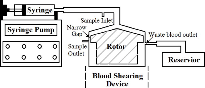
Figure 1.

The diagram of the blood shearing system, including a syringe pump used to control the flow rate, 140ml syringe, blood shearing device (Hemolyzer-L) with 150μm narrow gap between the inner rotor and the outer housing, sample inlet, sample outlet, reservoir and tubing.
