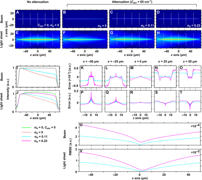
Fig. 2. Principle of attenuation-compensation for a Bessel light sheet.

Simulated xz intensity profiles for a flat-top Bessel beam without (A) and with (B) attenuation (Cattn = 65 cm−1) and with partial (C; σB = 0.11) and full (D; σB = 0.22) attenuation-compensation. (E to H) Light-sheet cross sections resulting from digital scanning of the Bessel beams shown in (A) to (D). (I and J) Peak transverse intensity as a function of longitudinal coordinate for the Bessel beams (A to D) and Bessel light sheets (E to H), respectively. The intensity is normalized to the start of the propagation-invariant region (x = −57.5 μm). (K to T) Comparison of Bessel beam and light-sheet transverse profiles with and without attenuation-compensation at x = −50 μm (K and P), −25 μm (L and Q), 0 μm (M and R), 25 μm (N and S), and 50 μm (O and T). (U and V) RMSE between Bessel beam and light-sheet transverse profiles with and without attenuation-compensation as a function of longitudinal coordinate.
