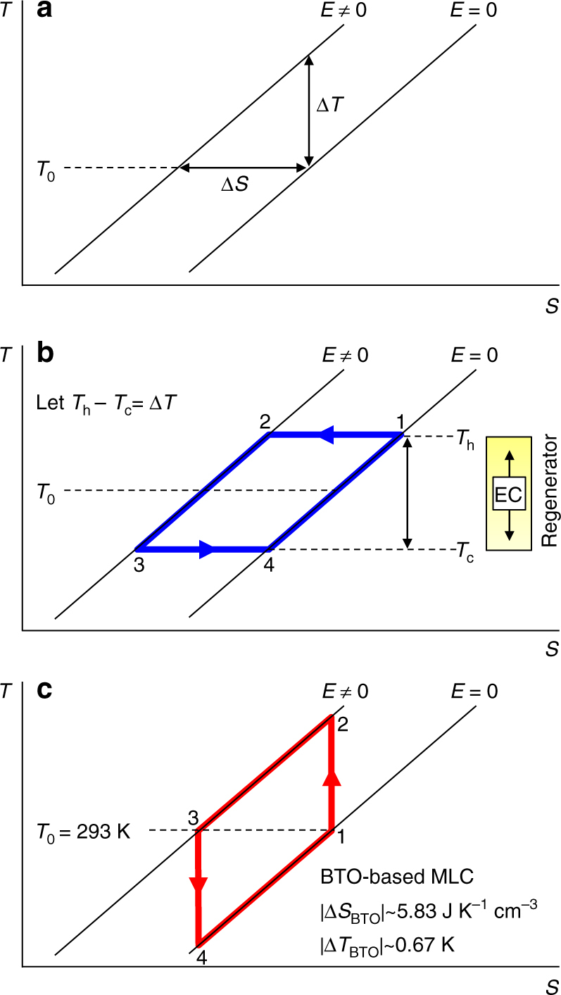
Fig. 1.

Simplified EC materials performance and resulting refrigeration cycles. a Near and at optimum starting temperature T0, we assume that one can achieve the maximum adiabatic temperature change ΔT, and the maximum isothermal entropy change ΔS, due to a change of applied electric field E. For the performance schematised in a, we show b an Ericsson cycle (1→2→3→4) where a thermal gradient in a fluid regenerator permits the separation of Tc (at which heat is absorbed) and Th (at which heat is expelled), and c the Brayton cycle (1→2→3→4) that we realize experimentally using two BTO-based MLCs, C1 and C2. Values for |ΔTBTO| and |ΔSBTO| describe the BTO layers alone
