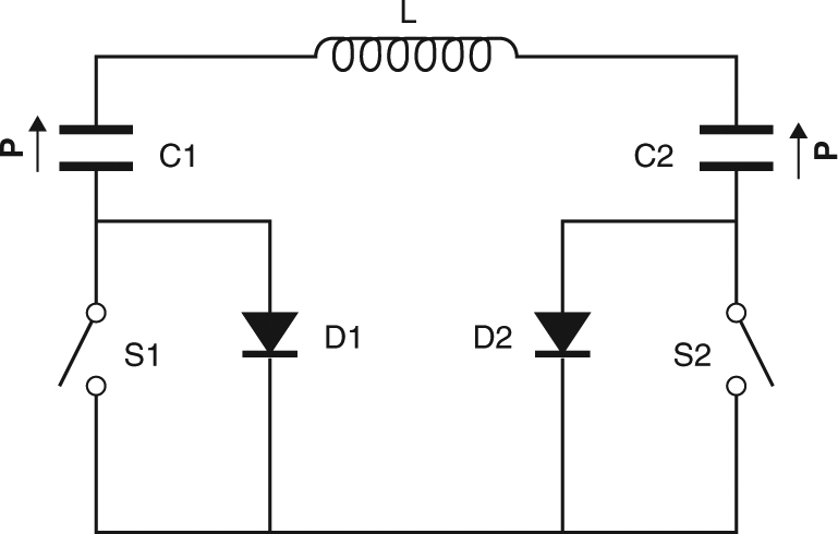
Fig. 3.

Circuit for the demonstration of energy recovery. Electrical energy was passed via inductor L between EC capacitors C1 and C2, which are poled ferroelectric MLCs with a variable polarization P of finite magnitude and fixed direction. Switches S1 and S2, and diodes D1 and D2, prevented resonance so that heat could flow between each charge-transfer event (see Methods). For simplicity, we do not show the Sourcemeter used to inject the initial charge into C1 and subsequently measure its voltage, or the Sourcemeter used to measure voltage across C2
