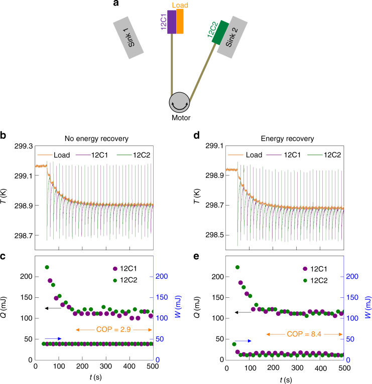
Fig. 5.
EC prototype without and with energy recovery. a Device schematic with EC plates 12C1 and 12C2, each based on 12 MLCs. Data are presented (b, c) without energy recovery and (d, e) with energy recovery. b, d In a given half cycle, each plate (whose temperature is given by the green or purple data) underwent rapid adiabatic EC cooling before slowly absorbing heat from the load, whose temperature Tc (orange data) fell by 0.26 K with respect to starting temperature Th on reaching the steady state around 250 s after start-up at time t = 40 s. c, e For each half cycle, we show the heat Q absorbed by the cold plate from the load, and the work W done to charge the other plate back to 70 V at the sink (where it thus dumps heat)

