Figure 1.
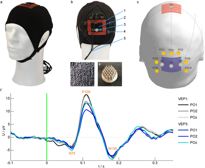
The design of the bifunctional cap was verified by recording VEPs during tDCS. (a,b) Photos of the cap with cap components: 1 – Silicone frame to prevent electrolyte diffusion; 2 – Textile stimulation electrode; 3 – Snap fastener for electrically connecting the textile stimulation electrode; 4 – Dry EEG electrode; 5 – EEG electrode cables. (c) Scheme of the positions of stimulation electrodes: anode (red) over Cz, cathode (blue) over Oz, and EEG recording electrodes (yellow) according to the international 10/10 system56. Dotted lines indicate auxiliary lines for electrode positioning. (d) The textile stimulation electrode consists of silver-coated threads integrated into the cap fabric. (e) Dry polyurethane-based EEG electrodes consisting of 30 pins coated with Ag/AgCl were integrated in the cap. (f) Average VEP with the components N75, P100 and N135 of one participant for different channels before (VEP1) and during (VEP3) tDCS. The green line at zero indicates the time of the visual stimulus. | EEG – electroencephalography; tDCS – transcranial direct current stimulation; VEP – visual evoked potential.

