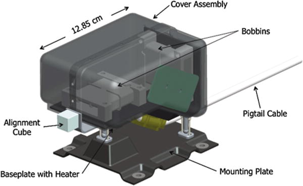
Fig. 9.

CAD drawing of a SPP MAG sensor, showing the composite structure supporting the two bobbins and electronics board (green) inside the composite cover. Also seen are two of the three kinetic mounts supporting the sensor on the composite 4-hole mounting plate, the alignment cube, and the pigtail harness that connects to the spacecraft harness
