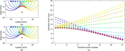
FIG. 4.
(Color online) Comparison of the sampling scheme for focused virtual source beamforming and REFoCUS beamforming. (a) Diagram of the transmit wavefield from 11 elements (upper solid markers) when the wavefront converging toward the focus (central solid marker) intersects the selected spatial point (black circle). Each spherical wave originates from the matching source element. (b) Diagram of the transmit wavefield at a later point in time after the converging wavefront has passed the selected point, which now intersects the trailing waves. (c) The virtual source (open circles) and REFoCUS (filled dots) samples through time required to beamform the signal for a single receive channel and the selected spatial location. The lines connect the samples corresponding to each recovered source element.

