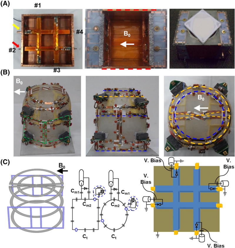
FIGURE 1.
Eight-channel Tx-only array, eight-channel Rx-only array and breast phantom. A, One side of 2 × 2 TTT array showing four excitation ports (red arrow and numbers) with tuning rod (yellow arrow) and assembled Tx-only array with RF shield box (red dotted lines). Tuning and matching can be achieved by pushing/pulling the inner copper rods; this is done once on the phantom and applied for all the human studies. A, right, Complete assembly of the eight-channel Tx-only and eight-channel Rx-only array and breast phantom located at the top of the RF coil. B, Picture of eight-channel Rx-only array in three planes. Four loops were tapered orthogonal to B0; two are showing (green dotted box) and two are tapered on the opposite side of the frame. An additional four loops were tapered in the coronal plane, three loops (blue dotted lines) are located 35 mm apart and a saddle loop (yellow dotted line) was located at the bottom. C, Schematic diagram of Rx-only and Tx-only arrays. The first panel shows the 3D layout of the eight-channel Rx-only array that was tapered in the acrylic frame (first panel in B). The second and third panels show the circuit diagram of the Rx-only array. Capacitors used in the coil loop for resonance frequency tuning (Ct) varied between 8 and 12 pF, whereas capacitors used for 50 Ω matching were 64 pF at Cm1 and 12–18 pF at Cm2. The fourth panel shows Tx-only pin connections and the detuning circuits used for active detuning during signal reception

