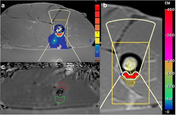
Fig. 2.

a T1-weighted image showing a lamb leg sample placed on a gelpad for sonication, with the heated region indicated by a colour overlay of the temperature map derived from PRFS (red pixels > ~60 °C). The sonicated cell (yellow ellipsoid) is shown magnified for greater clarity in (b), with the heated region shown in units of thermal dose (red pixels > ~400 equivalent minutes (EM)). The white line indicates the 240 EM at 43 °C thermal dose contour. ROI positions representing the heated region on the relevant slice of the ADC map (green outline), and a control region placed distally (red outline) are shown in (c)
