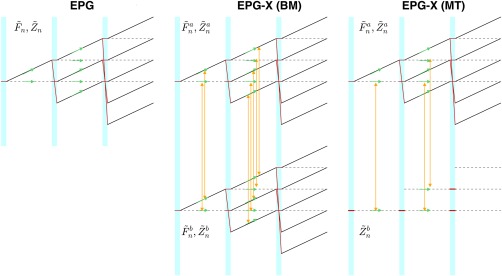
Figure 1.

Left: Overview of single‐compartment extended phase graph (EPG) algorithm. states are represented by dotted lines, by solid black lines. Blue‐shaded regions correspond to application of radiofrequency (RF) pulses. Red lines trace how states are mixed by the action of RF pulses. Green arrows depict relaxation effects, which occur individually to each state during the period between RF pulses. Middle: The EPG‐X (Bloch‐McConnell) approach consists of two separate EPGs. The RF pulses have the same effect as EPG. During evolution periods, relaxation (green arrows) and exchange (yellow arrows) both occur. Exchange links each state to its equivalent in the other compartment (i.e., ). Right: The EPG‐X magnetization transfer (MT) model has a reduced second compartment represented only by The RF pulses directly saturate these states (Eq. (14)), and they exchange directly with their equivalents in compartment a. For clarity, in all diagrams, relaxation and exchange effects are only depicted for the periods following the first two RF pulses. Although depicted by separate arrows, relaxation and exchange processes are governed by single combined operations.
