
Fig. 2. One-way Klein tunneling in nonreciprocal photonic topological insulator.
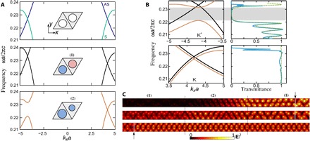
(A) Dispersion bands for a symmetric (nondimerized) structure of nonmagnetized rods (μ = 2, κ = 0) (top), a nonreciprocal PT-preserving crystal where cylinders of equal radii are magnetized in opposite directions (μ = 2, κ = 0.6) (middle), and a nonreciprocal PT-violating crystal where cylinders of slightly detuned radii are magnetized in the same direction (parameters are as in Fig. 1) (bottom). (B) Photonic bands near K and K′ points (left) and transmission coefficients (right). Top and bottom panels correspond to the backward and forward wave propagation, respectively. Numerically calculated transmission is plotted with a blue line. The analytically retrieved dependence with second-order correction in k·p method is shown with a green dashed line. The fitting parameters of the spectra extracted from the numerically calculated band diagrams are as follows: At the top (K′ valley), the frequency of the Dirac crossing at the K′ point ω0a/2πc = 0.233, and Fermi velocity vD/2πc = 0.020. In domain (1), u1 = 0, m1 = 0, α1 = −0.12vD, β1 = 0.54vD; in domain (2), u2a/2πc = −0.007, m2a/2πc = 0.005, α2 = −0.005vD, β2 = 0.06vD;. At the bottom (K valley), parameters are the same as those in domain (1) at the K′ valley, except that the frequency of the Dirac crossing at the K point becomes ω0a/2πc = 0.228, and in domain (2), m2 = 0, u2a/2πc = −0.004. αi, βi are the coefficients of in the effective Hamiltonian with their numerical values expressed in term of vD. (C) Simulated electric field intensity |E|2 distributions in the strip for backward (top and middle) and forward (bottom) wave propagation. The strip consists of three domains: Domain (1) is the nonreciprocal PT-preserving honeycomb lattices and separated by domain (2), which is composed of the inequivalent-sites lattice with magnetic field applied perpendicular to the lattice, and domains (1) and (2) contain 2 × 42 and 2 × 12 unit cells, respectively. The boundaries of three crystal regions are marked by black vertical lines. The modes are excited by current sheets at cuts indicated by the arrows and white lines.